Features and Operation of the KA Mount
- Lenses:
- SMC Pentax-A
- Bodies:
- A-Series, P-Series
- Compatibility Issues:
- Bodies in this group are usable with the FAJ lenses only in Tv and P operating modes. Lenses in this group, with the aperture ring away from to the “A” setting are are virtually unusable with bodies featuring the “crippled” KAF mount. There are no limitations when the aperture ring is set to “A”.
Overview
In 1983 Pentax introduced the KA mount — their second modification of the original K-mount. The first one was in 1981 with the AF-capable KF mount. That mount, however, was commercially unsuccessful, and led Pentax to decide against any further AF developments. For this reason, the KA mount is manual-focus-only — an extension of the original K-mount and not of the KF.
From a user’s point of view, the most important new feature of the KA mount is the “A” setting on the aperture ring of the lens. When this setting is not engaged, that is when a numerical f-stop is selected, there is no difference between the KA mount and the original K-mount. When the “A” setting is engaged, however, the following two additional operating modes are available:
- Shutter Priority (Tv) — the photographer sets the desired shutter speed, and the body calculates and sets the appropriate f-stop.
- Program (P) — the body sets both the f-stop and the shutter speed automatically. When the scene’s brightness allows multiple f-stop/shutter-speed combinations, the body chooses the one that is closest to its program curve.
Operation
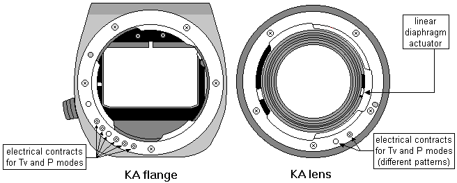
The KA mount differs from the original K-mount in three ways.

Figure 1. Diagram of the KA mount.
Linear Operation of the Diaphragm Actuator
The least-noticeable change is in the movement of the diaphragm actuator. In the original K-mount its displacement is proportional to the diameter of the diaphragm opening. In the KA mount, it is proportional to the area of the diaphragm opening, and thus to the selected f-stop. This leads to an identical stop-displacement between any two consecutive f-stops, and thus greatly simplifies the operation of the body in the Tv and P operating modes. All KA lenses have the same stop-displacement.
The diaphragm actuator’s change in operation does not lead to any incompatibilities with older camera bodies. This is because the diaphragm release of these bodies always moves all the way up, and allows unrestricted travel of the lens’ diaphragm actuator.
“A” Setting on the Aperture Ring
The lens aperture ring has an additional setting that is marked with an “A”. It is always the left-most aperture setting, and therefore functions as the lens’ narrowest f-stop. Because of this, when the “A” setting is engaged, the lens internal mechanics pull the diaphragm blades towards their “as closed as possible” position. On the other hand, when the lens is mounted on a camera body, the diaphragm release counteracts the lens mechanics, and keeps the diaphragm fully open.
When the “A” setting is not engaged, either the M or the Av operating modes are engaged, and the lens operates as if it were an original K-mount lens. When the “A” setting is engaged, the body is responsible for setting the picture-taking aperture. This happens in two steps. First, the body calculates how many f-stops the lens must be closed. Second, this number is multiplied by the stop-displacement (!!!), and the lens’ diaphragm actuator is allowed to close down only by that amount.
Electric Lens-Body Communication
The KA mount requires body-lens communication that cannot be accomplished via the mechanical couplings of the original K-mount. First, in order to know when to use the Tv or P operating mode, the body needs to be able to determine if the lens aperture ring is set to “A”. Second, after the body measures the scene’s brightness and determines how many stops the lens should be closed, it must know if the lens can be closed that many stops. Finally, in the Tv and P operating modes, the higher-end KA bodies display the picture-taking f-stop in the viewfinder. In order to support this feature, the body needs to know the absolute value of the lens widest f-stop.
Pentax implemented all of the above functionality by adding six electrical contacts to the flat surface of the body and lens mounts. These contacts are located in different positions from those of the KF mount, and therefore do not lead to any incompatibilities.

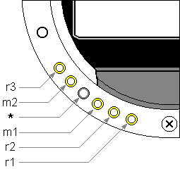
Figure 2. Detail from a KA-mount camera body.
On the body mount, the “*” contact is slightly recessed. On the lens mount, “*” is a small pin whose head can be raised or lowered depending on the position of the lens aperture ring. When a numeric f-stop is selected, the pin’s head is lowered so that it does not make contact with body’s “*” contact; when the “A” aperture setting is engaged, the pin’s head is raised, and it makes electrical contact with the body’s “*” contact.
The remaining five contacts are easily seen on the body. They look like small, slightly-protruding, ball-bearings. The lens-mount contacts are of two types: conducting and non-conducting. The non-conducting contacts are small plastic circles. The conducting contacts usually cannot be seen, because it is the (metal, and thus conducting) mount that fulfills their role. In rare cases, the lens mount has five holes, some of which are filled with plastic, and some with a golden metal. The golden metal and the plain “mount” contacts seem to have identical functionality.
Inquiring Minds Want to Know
The conducting/non-conducting pattern that the lens contacts form is decoded by the body as the lens’ narrowest aperture and number of f-stops. George de Fockert deciphered the pattern by cycling through all possible combinations on a ProgramA in program mode and looking at the minimum and maximum apertures shown in the viewfinder.
The table below shows the lens contact patterns in the following order r1r2m1*m2r3 where each contact is either metal (represented by 1) or plastic (represented by 0).
| Aperture Range | f/16 | f/22 | f/32 | f/45 |
|---|---|---|---|---|
| — | 110*01 | |||
| — | 110*00 | |||
| f/1.2 | 100*01 | 111*11 | ||
| f/1.4 | 100*00 | 111*10 | ||
| f/1.7 | 010*01 | 101*11 | 110*11 | |
| f/2.0 | 010*00 | 101*10 | 110*10 | |
| f/2.5 | 000*01 | 011*11 | 100*11 | 111*01 |
| f/2.8 | 000*00 | 011*10 | 100*10 | 111*00 |
| f/3.5 | 001*11 | 010*11 | 101*01 | |
| f/4.0 | 001*10 | 010*10 | 101*00 | |
| f/4.5 | 000*11 | 011*01 | ||
| f/5.6 | 000*10 | 011*00 | ||
| f/6.7 | 001*01 | |||
| f/8.0 | 001*00 |
Aparently r1r2r3 encode the aperture range in half stops starting at 5.0 and going up: 000 = 5.0, 001 = 5.5, 010 = 6.0, 011 = 6.5, 100 = 7.0, 101 = 7.5, 110 = 8.0, and 111 = 8.5 stops; m1m2 encode the minimum aperture: 00 = f/16, 01 = f/32, 10 = f/45, and 11 = f/22. The minimum aperture of f/16 is strange, since only screw mount lenses have f/16 as minimum aperture.
The correctness of the above hypotheses is confirmed in several lens service manuals distributed by Pentax. There they call the contacts F01 FCM A/M FCL F02 F03 instead of r1r2m1*m2r3, but all the rest is identical. A/M seems to stand for “Auto/Manual”.
Displaying Aperture in the viewfinder
In the Tv and P operating modes the body decides how many f-stops the lens will be closed down during the exposure. Consequently, knowing the narrowest aperture and the number of f-stops allows the higher-end bodies to calculate and display the selected f-stop.
But why does this not happen in the M and Av modes? After all, knowing the positions of its stop-down coupler, the body should be able to calculate how many f-stops the lens is closed down. Knowing the narrowest aperture and the number of f-stops, the body could calculate the widest aperture, and then the manually-selected f-stop. Yes, but only for prime lenses! Variable-aperture zooms have fixed contact patterns, and can therefore only indicate a fixed aperture range. In this case, the incorrect f-stop may be displayed in the viewfinder, and I guess that because of this, Pentax left the feature completely out. Note that due to the TTL exposure metering, the film will be exposed properly regardless of the fact that the f-stop’s numerical value may be calculated incorrectly.
The Tamron KA Adaptall Mount
When Joachim Hein read the above discussion, he immediately understood the roots of the exposure problems that some Adaptall lenses have. These are all “slow” lenses with minimum aperture setting of f/22 and an “AE” setting or f/32 and no “AE” setting In the latter case, f/32 is converted to “AE”). “AE” is the Tamron equivalent of the Pentax “A” setting. Looking in the second column of the table above, we see that there is no contact pattern for lenses with apertures ranging between f/4.5 or slower and f/22. Tamron solves this by making the Adaptall mount indicate a maximum aperture of f/4 and warning in the mount manual that the photographer must watch the aperture read-out in the view-finder (not available with P30/P50!) to ensure that only values within the true aperture range are used.
Multi-Segment Metering
No KA body implements multi-segment metering, so we delay discussing it to a later point. However, it is worth pointing out that in order to implement the Tv and P metering modes, Pentax did implement all three prerequisites for multi-segment metering:
- constructing all lenses to know their aperture range,
- constructing the mount to transfer the aperture range,
- redesigning the mount so that the body can easily determine the difference in f-stops between the widest and the currently-selected aperture.